
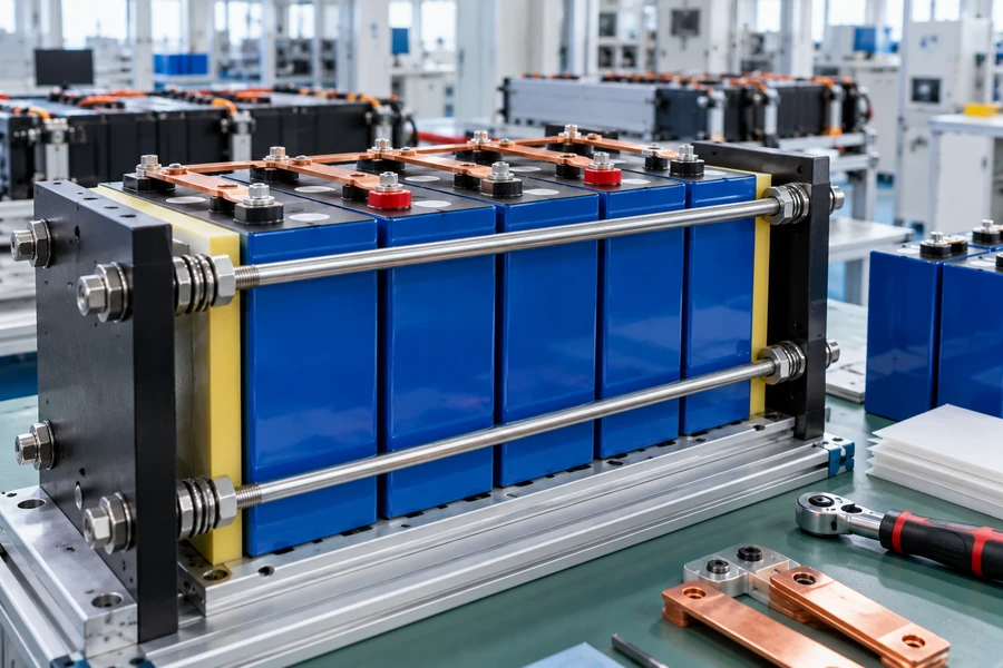
](https://voltcrave-battery.com/wp-content/uploads/2026/10/Do-LiFePO4-Prismatic-Cells-Need-Compression.webp)
Large LiFePO4 prismatic cells expand and contract during operation, so leaving them completely unsupported can create mechanical movement, swelling, and stress inside a battery pack.
Many large-format LiFePO4 prismatic cells should be installed with controlled mechanical restraint or compression when their manufacturer specifies it. Proper restraint can control swelling and maintain mechanical stability, but the correct force is cell-specific. Too little restraint may allow excessive movement, while excessive or uneven compression can increase resistance, damage cells, or reduce performance.
LiFePO4 prismatic cells need controlled support, not maximum compression. Proper design uses defined preload, expansion allowance, and uniform force distribution to manage swelling safely effectively.
Why Do LiFePO4 Prismatic Cells Need Compression?
Prismatic cells change mechanically as lithium moves through their electrode materials, and additional irreversible expansion can develop as cells age.
Controlled compression helps manage the dimensional changes of large prismatic LFP cells and maintain stable interfaces inside the battery. Research on commercial prismatic LFP cells shows that deliberate mechanical loading is used to control deformation, while moderate pressure can improve internal contact. However, excessive pressure can restrict ion transport, increase resistance, and accelerate unwanted reactions.
A large prismatic cell consists of more than an aluminum box filled with energy.
Inside it are:
electrode layers,
separator material,
electrolyte,
current collectors,
and internal connections.
During charging and discharging, electrode dimensions change.
Over thousands of cycles, aging processes can create additional irreversible expansion.
A 2025 study of commercial prismatic LFP cells describes how controlled loading can help stabilize internal interfaces and reduce problems associated with uncontrolled deformation. The same research emphasizes that compression has an optimum range: moderate loading can be beneficial, while excessive loading can narrow pores and increase internal resistance.
So compression has two sides:
Insufficient Mechanical Support → Excessive Movement and Swelling
Excessive Compression → Unwanted Mechanical and Electrochemical Stress
The objective is to remain inside the cell manufacturer's validated mechanical operating window.
Do All LiFePO4 Prismatic Cells Require the Same Compression Force?
No. There is no universal compression force that should be applied to every LiFePO4 prismatic cell.
Compression specifications vary by cell model, dimensions, internal construction, capacity, state of charge, age, and module design. A force specified for one 280 Ah cell should not automatically be used for a 100 Ah, 314 Ah, 560 Ah, or another manufacturer's cell. Always use the latest technical documentation for the exact cell model.
This point is especially important because numbers such as:
300 kgf
or:
12 psi
are frequently repeated in battery discussions.
They are not universal LFP standards.
For example, published copies of EVE's LF280K specification show cycle-life testing performed under approximately 300 kgf compression force. That describes a defined test condition for that particular cell and specification, not a rule for every prismatic LiFePO4 battery.
A published specification for EVE's much larger MB56 cell illustrates why universal numbers can be dangerous. That document gives a recommended grouping compression-force range of approximately 1,500 N to 12,000 N, with a separate instantaneous maximum specification.
These numbers are very different because the cells and designs are different.
The correct rule is therefore:
Manufacturer Specification > Internet Rule of Thumb
Is 300 kgf the Correct Compression Force for LiFePO4 Cells?
It can be a valid value for particular cells and test conditions, but it should not be treated as a universal target.
The frequently cited 300 kgf figure comes from specifications and test fixtures used for certain large prismatic cells. For example, published EVE LF280K documentation specifies approximately 300 kgf for particular cycle-testing conditions. That does not mean every LFP cell should be compressed to 300 kgf during pack assembly.
To understand this, we need to separate:
Force
from:
Pressure.
Force may be expressed in:
N,
kgf,
or lbf.
Pressure is:
Pressure = Force ÷ Area
Therefore, applying the same 3,000 N force to two cells with different face areas produces different pressure.
For example, suppose:
Cell A face area = 0.035 m²
and:
Compression force = 3,000 N
Then:
3,000 ÷ 0.035
≈ 85,700 Pa
or:
≈ 85.7 kPa
But if another cell has a much larger face, the same force produces lower pressure.
This is why copying a force number without considering cell geometry is poor mechanical design.
More importantly, the exact manufacturer's module-design specification may not be identical to the compression used during laboratory cycle testing.
A cycle-life test fixture tells us how a published performance result was obtained.
A module-design recommendation tells us how the cell should be integrated into an actual product.
Those are related, but they are not necessarily identical specifications.
What Happens If LiFePO4 Prismatic Cells Are Not Compressed?
The answer depends on the cell and operating conditions, but uncontrolled expansion can affect mechanical stability and aging.
Without adequate restraint, a prismatic cell can expand and contract more freely during cycling. Research on lithium-ion cells shows that unconstrained cycling can promote swelling, structural deformation, gas generation, loss of electrode contact, and faster capacity degradation in some cell designs. Proper mechanical constraint can help preserve internal structure.
This does not mean:
Uncompressed Cell = Immediate Failure.
A cell can still charge and discharge without a compression fixture.
The question is whether it will reproduce the:
cycle life,
mechanical behavior,
and dimensional stability
expected in its intended module design.
Research published in 2025 comparing constrained and unconstrained prismatic lithium-ion cells found that unconstrained operation increased swelling and structural degradation, while mechanical constraint helped preserve internal integrity and extend useful cycling under the study conditions.
For a battery pack, uncontrolled dimensional changes can also affect components outside the cell.
For example, repeated movement can place additional stress on:
busbars,
terminal connections,
temperature sensors,
insulators,
cell separators,
and module structures.
This is one reason industrial battery modules normally treat mechanical design as part of the complete cell integration problem rather than simply placing loose cells in a box.
Can Too Much Compression Damage LiFePO4 Cells?
Yes. More compression is not automatically better.
Excessive compression can create undesirable mechanical stress, restrict electrode and separator pores, increase ionic resistance, change electrochemical behavior, and potentially damage the cell case or internal structure. Research on prismatic LFP cells specifically describes compression as a balance: moderate pressure can be beneficial, while excessive pressure becomes counterproductive.
This is one of the most important concepts in battery mechanical design.
Imagine three situations:
| Mechanical Condition | Possible Result |
|---|---|
| Too little restraint | Excessive movement or swelling |
| Correct controlled restraint | Stable module structure and managed expansion |
| Too much compression | Increased stress, resistance, or cell damage |
The relationship is not:
More Pressure = More Cycle Life
Instead, it is closer to:
Correct Pressure Window = Better Mechanical Control
Research into lithium-ion cell compression has found similar trade-offs. Compression can improve electrical contact, but excessive pressure can increase transport resistance and other losses.
This also explains why tightening threaded rods by feel is not a reliable engineering method.
Bolt torque does not translate perfectly into cell-face compression because the result depends on:
thread friction,
washer friction,
plate stiffness,
rod geometry,
cell dimensions,
and assembly tolerances.
A mechanically validated design should know what force or displacement it is trying to achieve.
Should Compression Be Constant or Fixed?
This is more complicated than simply choosing rigid end plates.
Prismatic cells change thickness with SOC, temperature, and aging, so a fixed-distance structure and a constant-force structure behave differently. A rigid fixture may produce increasing pressure as cells expand, while springs or other compliant elements can allow controlled movement while maintaining a more predictable force range. The preferred design depends on the cell specification.
This creates two broad mechanical approaches.
Rigid Constraint
A stack can be placed between stiff end plates connected by:
threaded rods,
bolts,
steel bands,
or a rigid module frame.
The distance between the end plates changes very little.
As cells expand:
Force Can Increase.
Compliant Constraint
A system can incorporate:
springs,
Belleville washers,
foam,
elastomeric pads,
or engineered compliant structures.
As cells expand:
The Structure Allows Some Movement While Controlling Force.
Neither approach is universally correct.
A 2026 Nature Energy study discussing stack pressure in lithium-ion cells notes that pressure changes with SOC and cell lifetime as battery materials change volume and mechanical materials creep.
For LFP specifically, recent research also demonstrates that pressure changes through aging and that the relationship between initial preload and later expansion force is not trivial.
Therefore, good pack design considers:
Beginning-of-Life Force
and:
End-of-Life Force.
Designing only for a new cell can create problems years later after irreversible expansion has accumulated.
Do LiFePO4 Cells Expand When Charging?
Yes, but the amount and behavior depend on the cell design and operating conditions.
Prismatic lithium-ion cells experience reversible dimensional changes with state of charge and irreversible expansion as they age. In LFP modules, expansion pressure can change with SOC, temperature, cycle history, state of health, and initial mechanical load, so pack structures should be designed for both normal cycling movement and long-term growth.
The cell therefore experiences two different forms of dimensional change.
The first is:
Reversible Expansion
The cell changes during charge and then partially contracts during discharge.
The second is:
Irreversible Expansion
The cell gradually becomes thicker or develops greater swelling force as it ages.
This distinction matters.
If the pack structure has no ability to accommodate long-term growth, compression forces may rise significantly over the system's life.
A published copy of EVE's MB56 specification, for example, explicitly tells module designers to consider cell swelling force and gives different force information associated with aging down to 60% SOH.
That is strong evidence that compression should be treated as a lifetime module-design problem, not just an assembly step.
Should There Be Spacers Between Prismatic LiFePO4 Cells?
Electrical insulation and mechanical spacing should be designed according to the pack architecture rather than assumed from compression alone.
Compression does not mean bare aluminum cell cases should simply be pressed together without considering insulation, thermal management, electrical isolation, dimensional tolerance, and cell movement. Pack designers may use insulating sheets, thermal interface materials, compliant pads, spacers, or cooling plates depending on the cell and module architecture.
Mechanical compression and electrical insulation solve different problems.
Compression manages:
mechanical movement and swelling.
Insulation manages:
electrical separation.
Thermal material manages:
heat transfer.
A complete module may therefore look conceptually like:
End Plate → Insulation → Cell → Interface → Cell → Interface → Cell → Insulation → End Plate
The exact materials vary.
The important point is that cells should not be compressed in a way that:
damages their protective film,
loads terminals incorrectly,
blocks safety vents,
creates short-circuit paths,
or interferes with thermal management.
EVE's official product information confirms that the company produces prismatic LFP cells for multiple mobility and energy-storage applications, but also notes that specific product performance depends on the particular product and application.
That reinforces the need to design around the actual cell specification.
Should You Compress Cells at 100% State of Charge?
Do not assume that maximum SOC is the correct assembly condition.
Compression force depends partly on cell thickness, and cell thickness changes with SOC. Manufacturers may define a specific SOC range when measuring dimensions, setting preload, or performing mechanical tests. The pack should therefore be assembled at the SOC and under the procedure specified for the particular cell rather than at an arbitrary full-charge condition.
For example, published EVE specifications for certain cells describe compression measurements or fixtures at specified intermediate SOC levels rather than simply at 100% SOC.
Why does this matter?
Imagine setting a rigid fixture when the battery is at its smallest operating thickness.
When the cells later move toward a state where they are thicker:
Compression Force Can Increase.
Now imagine setting the same fixture while cells are already relatively expanded.
The resulting preload may be completely different.
Therefore, the assembly procedure should specify:
SOC
initial cell thickness
fixture spacing
target preload
measurement method
allowable tolerance
rather than simply telling an assembler:
“Tighten the cells.”
Do Small Prismatic LiFePO4 Cells Need Compression Too?
Cell format alone does not determine the answer.
Large energy-storage prismatic cells often receive the most attention because their broad flat surfaces and high capacities make swelling-force management important, but smaller prismatic cells can also have mechanical integration requirements. Whether compression is required, optional, or unnecessary should come from the exact manufacturer's module-design guidance.
The word:
prismatic
describes shape.
It does not define:
capacity,
case construction,
electrode structure,
wall thickness,
swelling behavior,
or allowable pressure.
A:
100 Ah prismatic cell
and a:
560 Ah prismatic cell
may both use LFP chemistry.
But their mechanical designs can differ dramatically.
This is why I would never create one universal compression table based only on:
Ah capacity.
The relevant variables include:
cell dimensions,
large-face area,
case thickness,
electrode structure,
cell generation,
intended application,
SOC window,
temperature,
cycle rate,
and manufacturer limits.
Does Compression Increase LiFePO4 Cycle Life?
It can improve cycling performance under appropriately engineered conditions, but compression is not a universal cycle-life multiplier.
Controlled mechanical constraint can help maintain electrode contact and reduce deformation, and multiple studies have found benefits from appropriate pressure. However, cycle-life improvement depends strongly on cell construction and pressure level, while excessive pressure can produce the opposite effect. Compression should therefore reproduce the cell's validated module conditions rather than chase a higher cycle-life number.
This distinction is important when reading cell specifications.
Suppose a manufacturer publishes:
6,000 cycles to 80% capacity.
Then check the test conditions.
Were those cycles measured at:
25°C?
0.5C?
a defined SOC range?
with a fixture?
under a specified compression force?
Those conditions matter.
A published EVE LF280K specification, for example, associates its stated 25°C cycle test with a defined 300 kgf compression condition.
Therefore:
Cycle-Life Number Without Test Conditions = Incomplete Information
Compression is only one condition.
Temperature, charge rate, discharge rate, SOC window, depth of discharge, calendar aging, and cell consistency also strongly affect lifetime.
Is Swelling Always a Sign That a LiFePO4 Cell Has Failed?
No. Normal dimensional change and abnormal swelling should not be treated as the same thing.
Prismatic cells naturally experience some mechanical expansion through normal operation and aging, which is why module designers account for swelling force. However, unusual bulging, rapidly increasing deformation, leakage, venting, excessive temperature, or major differences between cells can indicate a problem and should not simply be corrected by tightening the compression fixture.
This is especially important for DIY packs.
A compression fixture is not a repair tool.
If a cell is visibly developing abnormal deformation, simply tightening the end plates can hide the symptom without addressing the underlying cause.
Potential issues may involve:
overcharge,
cell imbalance,
excessive temperature,
internal degradation,
gas generation,
or mechanical damage.
The BMS and mechanical structure serve different functions.
BMS → Electrical and thermal operating protection
Compression Structure → Mechanical control
One cannot replace the other.
How Should You Design Compression for a LiFePO4 Battery Pack?
Start with the exact manufacturer's mechanical specification, then design a structure that keeps force within that validated range throughout battery life.
A good compression system should distribute load uniformly across the large cell faces, maintain electrical insulation, avoid terminal and vent loading, accommodate manufacturing tolerances and cell expansion, and keep forces below the manufacturer's limits from beginning to end of life. Force, plate stiffness, expansion allowance, temperature, and serviceability should be considered together.
A practical design sequence is:
Cell Datasheet
→
Required Preload
→
Cell Face Area
→
Allowable Expansion
→
End-Plate Stiffness
→
Compliant Element if Required
→
Electrical Insulation
→
Busbar Movement
→
Thermal Design
→
End-of-Life Force Check
Plate stiffness matters because:
Uniform Compression ≠ Simply Applying Enough Total Force.
If a thin end plate bends, the center and edges of the cell may experience different pressure.
Likewise, busbars need to tolerate cell movement without transferring damaging loads into battery terminals.
That is why professional module design treats:
mechanical,
electrical,
and thermal
engineering as one system.
What Is the Difference Between Cell Compression and Cell Restraint?
These terms are often used interchangeably, but the distinction can improve battery design.
Cell compression means applying a defined preload or pressure to the cell faces, while restraint more broadly means controlling cell position and expansion within a module. A battery may therefore need strong mechanical restraint without requiring an arbitrarily high continuous compressive pressure.
I prefer the term:
controlled mechanical restraint
because it prevents the assumption that cells simply need to be squeezed.
The design objective is to:
maintain alignment,
control expansion,
support the cell faces,
protect electrical connections,
and keep the cell within its validated mechanical environment.
This leads to a much better engineering principle:
Do Not Ask “How Hard Should I Squeeze It?”
Ask:
“What mechanical boundary conditions does this exact cell require throughout its life?”
That is the real compression question.
My Insights: What Really Matters With LiFePO4 Cell Compression
Compression should be treated as part of battery-module engineering rather than a universal DIY rule.
The most important principle is to distinguish controlled restraint from excessive clamping. Large prismatic LFP cells can benefit from appropriate mechanical support, but pressure changes with SOC and aging, and cell manufacturers may specify very different preload ranges. A good module controls expansion throughout life without exceeding validated mechanical limits.
My First Insight: 300 kgf Is Not a Universal LiFePO4 Number
The commonly repeated:
300 kgf
figure is useful only when it belongs to the exact cell specification or test condition.
Published LF280K documents use approximately 300 kgf in particular cycle and fixture conditions.
Other cells can have very different recommendations.
Published MB56 documentation, for example, gives a much broader and larger model-specific grouping compression range.
So I would never copy one cell's compression value into another battery design.
My Second Insight: Beginning-of-Life Compression Is Only Half the Problem
A cell does not maintain exactly the same dimensions throughout its life.
Pressure can change with:
SOC,
temperature,
cycling,
and aging.
The correct module therefore needs to work at:
BOL — Beginning of Life
and:
EOL — End of Life.
A design that is perfect on day one but excessively tight after years of swelling is not a good compression design.
My Third Insight: Uniform Pressure Matters More Than Maximum Pressure
A large number on a force gauge does not guarantee good mechanical integration.
Pressure should be distributed across the large cell faces.
Bent plates, badly positioned rods, uneven pads, or local contact points can create:
high-pressure zones
and:
low-pressure zones.
Research into lithium-ion cells shows that homogeneous mechanical pressure can materially affect cell behavior.
Therefore:
Uniformity > Maximum Force.
My Fourth Insight: Compression Must Be Designed Together With Busbars and Cooling
Cells do not exist independently inside a battery module.
When they expand, their movement can affect:
busbars,
terminals,
cooling surfaces,
insulation,
and sensors.
A good mechanical design therefore asks:
Can the busbar tolerate movement?
Does the compression plate interfere with cooling?
Are cell surfaces insulated?
Can the safety vent operate?
Can individual cells be inspected or serviced?
Compression is therefore a:
Module-Level Design Decision
rather than a standalone cell modification.
My Fifth Insight: Do LiFePO4 Prismatic Cells Need Compression?
Many large-format LiFePO4 prismatic cells need controlled mechanical restraint or compression to manage normal expansion and reproduce the mechanical conditions intended by their manufacturer. However, there is no universal force or pressure for all cells. Use the exact cell manufacturer's current specification for preload, SOC, expansion allowance, maximum force, insulation, and module structure instead of applying a generic 300 kgf or 12 psi rule.
The simplest decision framework is:
| Question | Best Practice |
|---|---|
| Do prismatic LFP cells expand? | Yes, mechanically through operation and aging |
| Should they be left completely loose? | Not when the manufacturer specifies restraint |
| Do all cells require the same force? | No |
| Is 300 kgf universal? | No |
| Can too much compression be harmful? | Yes |
| Does SOC matter? | Yes |
| Does aging matter? | Yes |
| Should pressure be uniform? | Yes |
| Should terminals carry compression force? | No |
| What specification should you follow? | Exact cell manufacturer's current documentation |
My preferred design principle is:
Manufacturer Mechanical Specification → Controlled Restraint → Uniform Load → Expansion Accommodation → Lifetime Verification
not:
Prismatic Cell → Tighten Until It Cannot Move.
Conclusion
Many LiFePO4 prismatic cells benefit from controlled compression, but force is model-specific. Follow the cell manufacturer's mechanical limits instead of applying a universal pressure value.
](https://voltcrave-battery.com/wp-content/uploads/2026/10/What-Is-the-Best-Power-Station-for-Home-Backup-768x512.webp)
](https://voltcrave-battery.com/wp-content/uploads/2026/10/What-Is-an-Electrical-Control-Cabinet-768x512.webp)
](https://voltcrave-battery.com/wp-content/uploads/2026/08/Why-a-Movable-All-in-One-Energy-Storage-System-Is-the-Future-768x512.webp)