

](https://voltcrave-battery.com/wp-content/uploads/2026/08/What-Is-an-Energy-Management-Backup-Unit-for-Telecom-Base-Stations.webp)
Telecom base stations must remain online during grid failures, but inefficient power systems can increase diesel use, battery degradation, maintenance costs, and site energy expenses.
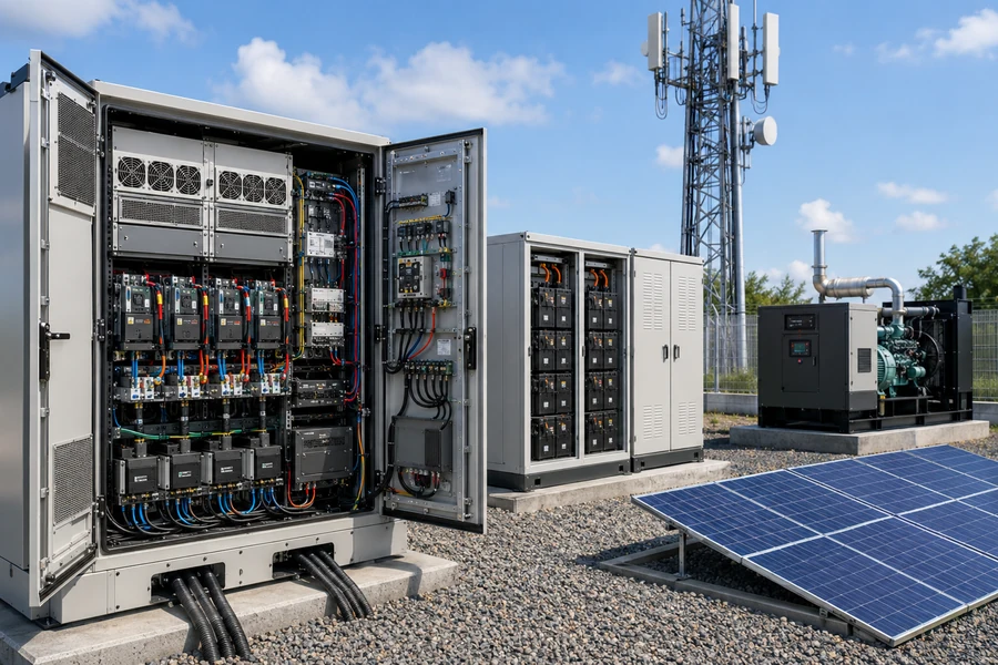
An energy management and backup unit for telecom base stations is an integrated power system that manages grid electricity, batteries, solar, and generators while supplying reliable DC power to telecom equipment. It combines rectifiers, battery storage, intelligent controls, protection, monitoring, and energy optimization to reduce outages, operating costs, and unnecessary generator use.
I see this unit as much more than a backup battery. A modern telecom energy system should decide where power comes from, when batteries charge or discharge, how renewable energy is used, when a generator starts, and how the site remains online during a grid outage. Modern site-energy platforms are increasingly extending batteries beyond emergency backup into peak shaving and broader energy optimization.
What Does an Energy Management & Backup Unit Do at a Telecom Base Station?
A telecom site needs continuous power for radio equipment, baseband processing, transmission equipment, cooling, monitoring, security, and other auxiliary loads. A grid interruption should not immediately interrupt communications.
The energy management and backup unit acts as the site's power hub. It converts AC grid electricity into telecom DC power, maintains the battery bank, supplies the load during outages, coordinates optional solar and generator sources, monitors operating conditions, and automatically selects the most appropriate energy source according to reliability, battery state, and operating cost.
A Typical Telecom Power Architecture
A simplified site can be represented as:
Utility Grid → AC Distribution → Rectifier → -48 V DC Bus → Telecom Loads
with additional energy sources connected around the DC power system:
Solar PV → DC/DC Converter → -48 V DC Bus
Battery Bank ↔ -48 V DC Bus
Diesel Generator → AC Input → Rectifier → -48 V DC Bus
Controller / EMS → Rectifier + Battery + Solar + Generator + Loads
The -48 V DC architecture is deeply established in telecommunications. ETSI EN 300 132-2 defines a nominal -48 V DC interface for ICT equipment and specifically recognizes power supplied by grid-fed rectifiers, solar DC/DC converters, generators, and battery backup.
This architecture gives the battery an important advantage during a grid interruption. Because the battery is already connected to the DC system, it can support the telecom load without waiting for a conventional standby generator to start.
The intelligent controller then determines what should happen next.
For example:
- Utility power is healthy.
- The rectifier supplies the telecom equipment and maintains the battery.
- Utility power fails.
- The battery immediately supports the DC load.
- The controller monitors battery state of charge.
- Solar continues contributing when available.
- If battery SOC falls below a defined threshold, the generator starts.
- The generator supplies the load and may recharge the battery.
- Grid power returns.
- The controller transfers back to normal operation and restores battery reserve.
This sequence illustrates why I treat the energy management system and backup system as one coordinated platform rather than separate devices.
Why Do Telecom Base Stations Commonly Use -48V DC Power?
Telecom sites have long relied on DC distribution because radios and other communications electronics can be supplied efficiently from a centralized rectifier and battery system.
-48 V DC is a standardized telecom power interface that allows rectifiers, batteries, renewable-energy converters, distribution equipment, and ICT loads to operate around a common DC bus. The architecture also makes battery backup straightforward because batteries can support DC loads directly without requiring an additional AC conversion stage during every outage.
The Rectifier Is the Core Grid Interface
When utility electricity is available, a telecom rectifier converts:
AC → DC
The rectifier system normally needs enough capacity to supply the telecom load while also supporting battery charging.
Modern telecom DC systems commonly use modular rectifier architectures. This means multiple rectifier modules can operate in parallel, allowing capacity to be increased as site power demand grows. Commercial telecom DC platforms also use intelligent controllers for monitoring and battery management.
Modularity is particularly useful for mobile networks because site power demand may change over time.
A site could begin as:
2G + 4G
and later become:
4G + 5G + additional radio sectors
The power system should be able to grow without replacing the entire cabinet.
I therefore check whether an energy management and backup unit supports:
- Modular rectifier expansion
- Multiple battery strings
- Solar inputs
- Generator interfaces
- Remote monitoring
- Additional DC loads
A well-designed power cabinet becomes infrastructure that can remain in service while the radio network evolves around it.
What Components Are Inside a Telecom Energy Management & Backup Unit?
A useful telecom backup unit combines energy conversion, storage, control, protection, and communications.
The main components normally include AC input protection, high-efficiency rectifiers, -48 V DC distribution, battery connections, BMS integration, an intelligent site controller, load breakers, metering, communications, temperature monitoring, and alarm outputs. Hybrid systems may additionally include solar converters, generator interfaces, smart load management, and remote energy-management software.
Key Components and Their Functions
| Component | Main function |
|---|---|
| AC input | Receives utility or generator power |
| Rectifier | Converts AC to regulated telecom DC |
| DC distribution | Supplies radio and transmission loads |
| Battery bank | Provides outage backup |
| BMS | Protects and monitors lithium batteries |
| Site controller | Coordinates power sources and operating modes |
| Solar DC/DC converter | Integrates photovoltaic generation |
| Generator controller | Starts/stops generator when necessary |
| Metering | Measures voltage, current, power, and energy |
| Sensors | Monitor temperature and environmental conditions |
| Breakers/fuses | Provide circuit protection and isolation |
| Communications | Sends alarms and operating data remotely |
| EMS software | Optimizes energy use across one or many sites |
The exact configuration depends heavily on site type.
A compact urban macro base station may require only:
Grid + rectifier + lithium battery
A remote off-grid station may require:
Solar + battery + generator + hybrid controller
A large 5G site may add advanced energy-management functions that use the battery during normal grid operation rather than reserving it exclusively for emergencies.
Ericsson has demonstrated this broader model at an energy-smart 5G site where solar, lithium-ion batteries, grid electricity, and intelligent energy management are coordinated. It has also demonstrated using site batteries for peak-power support rather than limiting them to outage backup.
What Is the Best Battery for Telecom Base Station Backup?
Historically, telecom sites relied heavily on lead-acid batteries. Lithium-ion, particularly LFP, has become increasingly attractive for new installations.
For many modern telecom base stations, I prefer LFP battery storage because it can provide high cycle life, compact installation, low routine maintenance, intelligent BMS monitoring, and better suitability for frequent energy-management cycling than traditional standby-only battery architectures. Lead-acid can still be appropriate where low acquisition cost and established local service are priorities.
Why LFP Changes the Role of the Telecom Battery
A traditional telecom battery may spend most of its life waiting for an outage.
Its operating pattern is:
Float → outage → discharge → recharge → wait
An intelligently controlled lithium battery can do more:
Backup + solar shifting + peak shaving + generator optimization + grid services
Ericsson describes modern ICT batteries as moving from purely backup resources toward dynamic energy assets. Its site-energy work includes using network-site batteries to reduce energy costs and potentially coordinate multiple sites as virtual power plants.
This changes how I size and evaluate the battery.
I no longer ask only:
How many hours can it provide during an outage?
I also ask:
- How many cycles can it tolerate?
- What SOC window should be reserved for emergencies?
- Can the BMS communicate with the site controller?
- Can it operate at the site's temperature?
- Can it charge from solar?
- Can it reduce generator runtime?
- Can it participate in peak shaving?
The battery becomes part of the site's operating strategy rather than simply emergency equipment.
How Much Battery Capacity Does a Telecom Base Station Need?
Backup sizing starts with site load and required autonomy.
I estimate telecom battery capacity from the site's average DC load multiplied by the required backup time, then adjust for usable depth of discharge, conversion losses, temperature, degradation, and design reserve. A 3 kW site requiring eight hours of backup needs at least 24 kWh of delivered energy before these margins are added.
A Simple Sizing Formula
A basic starting point is:
Required delivered energy = Site load × Backup hours
Suppose:
Average telecom load = 3 kW
Required autonomy = 8 hours
Then:
3 kW × 8 h = 24 kWh
If I assume 90% usable depth of discharge and 90% allowance for system efficiency and reserve effects in a simplified calculation:
Nominal battery ≈ 24 ÷ (0.90 × 0.90)
≈ 29.6 kWh
I would therefore initially evaluate a battery around 30 kWh or larger before making further corrections for temperature, aging, site growth, and the battery manufacturer's specified operating limits.
Different Sites Need Different Backup Times
| Site type | Example load | Example backup strategy |
|---|---|---|
| Small cell | <1 kW | Compact battery |
| Rural macro site | 1–3 kW | Several hours battery backup |
| Large macro/5G site | 3–8+ kW | Larger battery or hybrid backup |
| Unreliable-grid site | Variable | Battery + generator |
| Off-grid site | Variable | Solar + battery + generator |
| Critical communications site | Variable | Extended redundant backup |
These are architecture examples, not standardized requirements.
Actual telecom backup targets are determined by network criticality, operator policy, grid reliability, climate, maintenance access, and regulatory requirements.
A remote site that takes six hours for a maintenance crew to reach clearly needs a different resilience strategy from a rooftop station in a city with a reliable electrical grid.
How Does Solar Work With a Telecom Backup Unit?
Telecom base stations are attractive candidates for hybrid solar because they operate continuously and many remote sites have predictable electrical loads.
Solar can feed the site's DC power system through a DC/DC converter, serving telecom loads while excess energy charges the battery. The energy-management controller can prioritize solar, reduce grid purchases, limit generator runtime, and preserve a defined battery reserve for outages. This is particularly valuable at remote or weak-grid telecom sites. ETSI's -48 V interface explicitly recognizes DC power supplied from solar-system converters, while GSMA has documented mobile operators using standalone and hybrid solar solutions at network sites.
A Solar-First Operating Strategy
I might configure a remote station in this order:
Priority 1: Solar
Use available solar energy directly for the telecom load.
Priority 2: Battery
Use stored energy when solar is insufficient.
Priority 3: Grid or generator
Use conventional power when renewable energy and battery SOC cannot support the load.
At another site with a reliable but expensive grid, the order could be different:
Grid + solar → charge battery
Peak tariff period → battery discharge
Emergency reserve → always protected
The controller must balance economics against availability.
If I discharge the battery aggressively every afternoon to save money, I may have insufficient reserve when an outage begins at 7 p.m.
For telecom, network uptime must remain the first priority.
The energy-management algorithm should therefore maintain an emergency SOC reserve while optimizing the remaining battery capacity.
How Can Energy Management Reduce Diesel Generator Use?
Diesel generators remain important at many remote and unreliable-grid telecom sites, but operating them inefficiently can increase fuel, maintenance, and logistics costs.
An intelligent backup unit can reduce generator runtime by using batteries to cover shorter outages and low-load periods, starting the generator only when battery SOC reaches a defined threshold. When the generator does run, it can operate at a more useful loading point while simultaneously supplying the site and recharging the battery.
Battery-Generator Hybrid Operation
Without sufficient battery storage:
Grid fails → generator starts immediately
With battery storage:
Grid fails → battery supplies site
If power returns before the battery reaches its lower SOC limit:
Generator never starts
If the outage continues:
Battery reaches threshold → generator starts → site + battery charging
This strategy can avoid thousands of unnecessary short generator starts across a large telecom network.
GSMA has documented hybrid telecom installations combining lithium batteries with diesel generators, illustrating how mobile operators use batteries to reduce generator dependence rather than relying on diesel continuously.
For off-grid and weak-grid regions, I see this as one of the strongest economic arguments for intelligent energy management.
Fuel costs include much more than the fuel itself.
Operators may also face:
- Fuel transportation
- Theft
- Generator servicing
- Oil and filter replacement
- Site visits
- Spare parts
- Refueling logistics
A larger battery can sometimes reduce these operational expenses enough to justify a higher initial investment.
How Does Smart Energy Management Improve 5G Base Stations?
5G increases the importance of managing the power system dynamically because network infrastructure is becoming both more capable and more energy-aware.
Smart telecom energy management uses site-load data, battery SOC, electricity tariffs, renewable generation, weather information, and network demand to optimize power sources. Modern platforms can move beyond individual-site monitoring and coordinate groups of base stations, potentially using distributed batteries for peak shaving, demand response, and virtual-power-plant applications.
From Backup Controller to Energy Orchestrator
A traditional controller may perform simple rules:
Battery voltage low → start generator
A modern controller can make decisions using:
- SOC forecast
- Solar forecast
- Electricity price
- Expected network traffic
- Battery temperature
- Grid status
- Generator status
- Remote operator commands
Ericsson's Site Energy Orchestration platform illustrates this transition. It uses network and external information to optimize energy and can coordinate sites in virtual-power-plant-type applications.
I see this as an important future direction.
Telecom operators manage thousands of geographically distributed sites.
Each one may contain:
- A controllable electrical load
- A battery
- A grid connection
- Sometimes solar generation
Individually, one battery may be small.
Across 10,000 sites, the combined flexible capacity can become significant.
The backup asset may therefore provide value even when no outage occurs.
What Should I Look for in a Telecom Energy Management & Backup Unit?
Reliability comes first. A feature-rich controller has little value if it creates another single point of failure.
I evaluate a telecom energy management and backup unit by DC voltage compatibility, rectifier efficiency, battery capacity, BMS communication, redundancy, solar and generator integration, remote monitoring, environmental rating, protection, scalability, alarm functions, cybersecurity, and serviceability. The system should fail safely and continue powering critical telecom loads when communications or advanced optimization functions are unavailable.
My Telecom Power Selection Checklist
| Requirement | What I check |
|---|---|
| DC output | Compatibility with -48 V telecom loads |
| Rectifier architecture | Modular and redundant |
| Battery chemistry | LFP or appropriate alternative |
| Battery capacity | Meets required backup hours |
| BMS integration | SOC, SOH, alarms, temperature |
| Solar input | MPPT/DC converter compatibility |
| Generator control | Automatic start/stop |
| Load management | Priority and noncritical load control |
| Monitoring | Voltage, current, energy, SOC, alarms |
| Communications | SNMP/IP/other required interfaces |
| Remote management | Central NOC visibility |
| Expansion | More rectifiers and batteries can be added |
| Environment | Temperature, dust, humidity, outdoor rating |
| Protection | Breakers, fuses, surge protection |
| Security | Protected local and remote communications |
Commercial telecom DC platforms already combine high-efficiency modular rectifiers, distribution, controllers, battery management, and remote visibility, while outdoor telecom cabinets can integrate power systems, network equipment, battery backup, and thermal infrastructure.
I would also verify the standards applicable to the target market. ETSI EN 300 132-2 is an important reference for -48 V DC interfaces in telecom and ICT equipment, but it explicitly does not replace the separate safety standards relevant to the complete equipment and installation.
My Insights: What Is an Energy Management & Backup Unit for Telecom Base Stations
I believe the most valuable telecom backup solution is no longer a battery cabinet that waits passively for the grid to fail.
An energy management and backup unit for telecom base stations is an intelligent -48 V DC power platform that coordinates utility power, rectifiers, batteries, solar, generators, protection, and monitoring. Its primary job is maintaining network uptime, but modern systems can also reduce diesel consumption, optimize renewable energy, lower electricity costs, and use batteries more productively.
I Would Design the Unit Around Uptime First
My priority order is:
1. Keep the telecom load online
2. Protect sufficient battery reserve
3. Maximize renewable energy
4. Minimize generator operation
5. Reduce grid energy cost
6. Use spare flexibility for additional energy services
This order is important.
A telecom battery exists because losing power can mean losing network coverage.
Saving money should never create an unacceptable risk of battery depletion before an outage.
I Prefer a Modular -48V Platform
ETSI's -48 V interface remains an important reference point for telecom DC systems and explicitly accommodates multiple energy sources, including grid-fed rectifiers, solar converters, generators, and battery backup.
That makes a modular DC architecture particularly useful.
I can begin with:
Grid + rectifier + battery
and later add:
Solar
then:
Generator integration
then:
Advanced site-energy orchestration
without redesigning the radio equipment's basic power interface.
LFP Can Turn Backup Capacity Into an Operating Asset
Lithium batteries make it more practical to use telecom storage more frequently because the storage system can participate in normal energy optimization rather than remaining idle until an emergency.
Ericsson explicitly describes this evolution from backup batteries toward dynamic site-energy assets, including peak support and aggregated energy applications.
For me, that is the core change in modern telecom backup design.
The system is evolving from:
Power supply + emergency battery
into:
Intelligent distributed energy system
Remote Management Is Essential at Scale
A telecom operator may manage hundreds or thousands of sites.
I therefore want one central platform to show:
- Grid availability
- Battery SOC
- Battery SOH
- Site load
- Solar production
- Rectifier status
- Generator runtime
- Temperature
- Active alarms
- Energy consumption
Without this visibility, maintenance remains reactive.
With reliable monitoring, operators can identify deteriorating batteries, abnormal energy consumption, failed rectifier modules, cooling problems, and repeated grid outages before they create major network failures. Current commercial telecom DC systems emphasize this type of real-time network-power visibility and remote control.
My Preferred Architecture
For a new macro base station, my starting architecture would be:
Utility AC + optional generator
↓
Modular high-efficiency rectifiers
↓
-48 V DC bus
↔ LFP battery with BMS
← Solar MPPT/DC converter
↓
Radio + baseband + transmission + essential auxiliary loads
and above the complete system:
Intelligent Site Energy Controller / EMS
The EMS monitors every major energy flow and makes decisions without compromising the site's required emergency reserve.
That architecture can serve grid-connected, weak-grid, and hybrid telecom installations by changing battery capacity and energy-source configuration rather than rebuilding the basic power platform.
Conclusion
An energy management and backup unit keeps telecom base stations online while intelligently coordinating -48 V power, batteries, solar, grid electricity, and generators to improve reliability and energy efficiency.
](https://voltcrave-battery.com/wp-content/uploads/2026/08/What-Are-the-Key-Differences-Between-a-Solar-Battery-and-a-Regular-Battery-768x512.webp)
](https://voltcrave-battery.com/wp-content/uploads/2026/08/What-Is-a-Commercial-Battery-Storage-System-768x512.webp)
](https://voltcrave-battery.com/wp-content/uploads/2026/08/What-Is-the-Standard-Size-of-a-BESS-Container-768x512.webp)