
](https://voltcrave-battery.com/wp-content/uploads/2026/09/Large-Battery-Storage-Systems-Engineering-Grid-Integration-Industrial-Solutions.webp)
Large battery projects can stabilize grids and reduce industrial energy costs, but poor sizing, integration, thermal design, or controls can turn valuable storage capacity into an expensive underused asset.
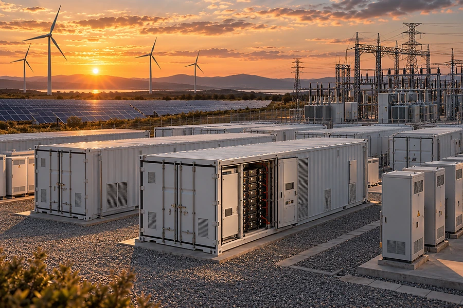
Large battery storage systems are MW- and MWh-scale energy assets designed for grid support, renewable integration, industrial peak management, backup power, and energy shifting. Successful BESS projects require coordinated battery racks, BMS, PCS, EMS, thermal management, transformers, protection, and grid controls, with power, duration, safety, degradation, and economics engineered around the actual application.
Large-scale storage is also moving quickly from a specialized grid technology into mainstream power infrastructure. In 2025, 108 GW of new battery storage capacity was deployed globally, 40% more than in 2024. Installed capacity was eleven times its 2021 level, and roughly 80% of new capacity was utility-scale.
What Is a Large Battery Storage System?
Large battery storage is more than a collection of battery cells connected to an inverter.
A large Battery Energy Storage System, or BESS, stores electrical energy at commercial, industrial, or utility scale and releases it according to grid or facility requirements. A complete system normally combines battery cells and racks with BMS, PCS, EMS, thermal management, fire protection, switchgear, transformers, monitoring, communications, and balance-of-system infrastructure.
The basic architecture can be represented as:
Battery Cells → Modules → Racks → Battery Enclosures
Then:
Battery → PCS → Transformer → Switchgear → Grid or Facility
Around those components are several control layers:
BMS + EMS + SCADA + Thermal Management + Protection
Each performs a different function.
The BMS monitors the batteries.
The PCS converts electrical power.
The EMS determines when and how the BESS operates.
The SCADA layer provides supervisory monitoring and integration with the broader site.
The transformer and switchgear connect the storage system safely to the required electrical voltage and network.
This distinction matters because the battery pack itself represents only part of a complete project's engineering and cost. NREL's utility-scale storage modeling includes the battery pack, inverter and balance-of-system equipment when evaluating complete BESS capital cost.
For large projects, I therefore treat the BESS as an electrical power plant rather than simply a large battery.
What Is the Difference Between MW and MWh in Large Battery Storage?
Confusing power with energy is one of the most common BESS sizing mistakes.
MW measures how much power a battery system can charge or discharge at one moment, while MWh measures how much energy it can store. The relationship between them determines storage duration: a 10 MW/40 MWh BESS can theoretically discharge at its full 10 MW rating for approximately four hours.
The basic equation is:
Duration = Energy ÷ Power
For example:
| BESS Power | Energy Capacity | Nominal Duration |
|---|---|---|
| 10 MW | 10 MWh | 1 hour |
| 10 MW | 20 MWh | 2 hours |
| 10 MW | 40 MWh | 4 hours |
| 10 MW | 60 MWh | 6 hours |
| 10 MW | 80 MWh | 8 hours |
| 50 MW | 200 MWh | 4 hours |
NREL models utility-scale lithium-ion storage across durations from 2 to 10 hours, specifically because power and energy are separate design and cost variables.
This distinction also affects cost.
Some project costs scale primarily with:
MWh
because more energy requires more battery cells.
Other costs scale more closely with:
MW
because higher power requires larger inverters, transformers, conductors, switchgear, and electrical infrastructure.
That is why a:
100 MW / 100 MWh
system is not economically equivalent to:
25 MW / 100 MWh.
Both contain 100 MWh.
But one must deliver four times the power.
How Are Large Battery Storage Systems Engineered?
Engineering should begin with the required service rather than a predetermined battery size.
Large BESS engineering starts by defining the load or grid problem, required MW, discharge duration, MWh, cycling frequency, connection voltage, environmental conditions, redundancy, and safety requirements. Engineers then select battery architecture, PCS topology, transformers, switchgear, protection, controls, thermal management, communications, and civil infrastructure around those requirements.
A utility may need storage for:
evening energy shifting.
An industrial plant may need:
peak shaving.
A data center may prioritize:
resilience.
A solar project may need:
curtailment reduction.
These applications produce different designs.
Suppose a factory normally draws:
8 MW
but reaches:
12 MW
for two hours.
The operator wants to limit grid demand to:
9 MW.
Required BESS power:
12 – 9 = 3 MW
Required theoretical energy:
3 MW × 2 h = 6 MWh
So the starting point is approximately:
3 MW / 6 MWh
before accounting for reserve, efficiency, degradation and operating margins.
Now compare that with a solar plant needing to shift:
20 MW
for:
4 hours.
Required theoretical energy becomes:
20 × 4 = 80 MWh.
Same technology.
Completely different BESS.
What Are the Main Components of a Large BESS?
The performance of a large storage project depends on the interaction of multiple subsystems.
The main components of a large BESS include battery cells and racks, Battery Management System, Power Conversion System, Energy Management System, thermal management, fire detection and protection, transformers, switchgear, auxiliary power, communications, SCADA, enclosures, and civil infrastructure. No individual component determines system performance by itself.
The battery provides energy.
The PCS determines how quickly that energy moves between DC storage and the AC network.
The BMS monitors parameters such as:
cell voltage,
current,
temperature,
SOC,
and abnormal conditions.
The EMS uses higher-level information including:
electricity prices,
grid signals,
facility demand,
renewable generation,
SOC,
and operating reserves.
A simplified control relationship is:
EMS → PCS → Battery
while:
BMS → Battery Protection
can limit or stop operation if battery conditions become unsafe.
Large projects also require auxiliary systems.
Cooling consumes electricity.
Fire detection requires sensors and controls.
Communications connect individual containers to site-level controllers.
Transformers raise or lower voltage.
Switchgear isolates equipment.
The result is an integrated electrical system, not merely a battery installation.
How Does a Large BESS Connect to the Grid?
Grid integration requires the BESS to behave as a controlled electrical resource rather than an isolated energy reservoir.
A grid-connected BESS typically uses bidirectional power conversion, transformers, switchgear, protection, metering, communications, and plant-level controls to exchange power with the electrical network. The system must satisfy interconnection requirements for voltage, frequency, reactive power, protection, fault response, and operating commands applicable to the specific grid and jurisdiction.
The power path can look like:
Battery DC
↓
PCS
↓
Low/Medium-Voltage AC
↓
Transformer
↓
Medium/High-Voltage Network
↓
Grid
Charging reverses the direction.
The EMS or plant controller may receive commands such as:
Charge at 20 MW
or:
Discharge at 50 MW.
The PCS then converts that command into controlled electrical power.
Grid integration can also involve:
active power,
reactive power,
frequency response,
voltage support,
and ramp-rate control.
This is one reason BESS has become valuable as renewable generation increases.
Storage can respond rapidly and change between charging and discharging without the fuel and mechanical ramping constraints of conventional generation.
What Is AC-Coupled vs. DC-Coupled Battery Storage?
The location of the battery relative to renewable-generation power conversion changes system architecture.
In an AC-coupled system, renewable generation and battery storage generally use separate power-conversion paths and connect on the AC side. In a DC-coupled system, PV and battery resources can share part of the DC infrastructure and potentially the inverter stage. Each approach has advantages depending on retrofit requirements, clipping recovery, equipment flexibility, and operating strategy.
A simplified AC-coupled solar project is:
Solar → Solar Inverter → AC Bus
and:
Battery ↔ PCS ↔ AC Bus
This architecture can be attractive for:
existing solar sites,
independent battery operation,
and:
flexible equipment selection.
A simplified DC-coupled system is:
Solar + Battery → DC Bus → Shared Power Conversion → Grid
One potential advantage is capturing solar energy that might otherwise be clipped because the PV array is producing more DC power than the inverter can export.
The battery can potentially absorb part of that energy.
However, DC coupling also creates additional design interactions between:
PV voltage,
battery voltage,
DC/DC conversion,
inverter sizing,
and:
controls.
Neither architecture is universally better.
The correct choice depends on the project.
How Do Large Battery Systems Support Renewable Energy?
Renewable generation and electricity demand rarely align perfectly in time.
Large battery systems support renewable energy by storing surplus solar or wind electricity and releasing it when generation falls or demand increases. Storage can reduce curtailment, shift renewable production into evening peaks, smooth output, provide grid services, and increase the usable value of variable generation without requiring generation and consumption to occur simultaneously.
Consider a solar facility producing:
100 MW
at midday.
Suppose the grid can accept only:
75 MW
for:
three hours.
Potential surplus:
100 – 75 = 25 MW
Surplus energy:
25 MW × 3 h = 75 MWh
A suitably designed BESS could capture part or all of that energy.
Later:
Battery → Grid
during the evening peak.
This changes the renewable profile from:
Generate Now → Use Now
to:
Generate → Store → Dispatch Later.
The market is increasingly using batteries for this purpose. IEA reports that most projects still cluster around approximately two hours of storage, but an increasing number can provide four hours or more as the value of flexibility rises in power systems with increasing PV penetration.
How Can Large Battery Storage Improve Grid Stability?
BESS can respond quickly to changes in grid conditions.
Large battery storage can support grid stability by rapidly changing active and reactive power in response to system conditions. Depending on its inverter and controls, a BESS can contribute to frequency response, voltage support, renewable smoothing, ramp management, congestion relief, reserve capacity, and other flexibility services.
Imagine grid frequency begins to fall because generation suddenly becomes lower than demand.
A BESS can respond by:
increasing discharge
or:
reducing charging.
When excess electricity exists, it can:
increase charging.
This bidirectional flexibility is valuable because the same asset can behave as:
Load
during charging
and:
Supply
during discharge.
But battery energy is finite.
A BESS providing:
100 MW
with:
100 MWh
contains approximately one nominal hour at full output.
A:
100 MW / 400 MWh
system provides approximately four hours.
Therefore, power-system planners must distinguish between:
fast response
and:
sustained energy support.
A high-power battery can stabilize short events even with modest energy capacity, while energy shifting requires substantially more MWh.
How Can Industrial Facilities Use Large Battery Storage?
Industrial BESS can address both electricity cost and operational resilience.
Industrial facilities use large battery storage for peak shaving, demand-charge management, time-of-use shifting, renewable self-consumption, backup support, EV charging infrastructure, microgrids, and power-management applications. The strongest projects often combine multiple compatible services rather than relying on a single savings mechanism.
Peak shaving is a common example.
Suppose normal factory demand is:
5 MW.
Production creates a peak of:
7 MW
for:
90 minutes.
Target grid demand:
5.5 MW
Required BESS output:
7 – 5.5 = 1.5 MW
Energy:
1.5 × 1.5 = 2.25 MWh
A storage system could discharge during the peak and recharge later.
Another industrial application is solar self-consumption.
Suppose a factory has:
10 MW of solar
but weekend production is low.
Instead of exporting all surplus electricity, the BESS can store part of it for later use.
For facilities with critical processes, storage can also provide resilience.
The project can therefore create:
Energy Savings + Renewable Value + Resilience.
NREL's commercial-storage modeling explicitly evaluates BESS across different power and duration combinations because both variables materially affect installed system cost.
How Does Large Battery Storage Work in a Microgrid?
A microgrid coordinates local generation, storage, loads, and potentially backup generation.
In a microgrid, large battery storage acts as a flexible energy buffer between generation and demand. It can charge from the grid or onsite renewables, discharge during high demand, support critical loads during outages, coordinate with generators, and help maintain local voltage and frequency when the microgrid operates in island mode.
A typical architecture could be:
Grid + Solar + BESS + Generator → Microgrid → Critical/Non-Critical Loads
During normal operation:
Grid + Solar → Loads
while the BESS performs:
peak shaving,
energy shifting,
or:
reserve management.
When the grid fails:
Microgrid Disconnects
Then:
BESS + Solar + Generator → Critical Loads
The battery can provide fast response.
The generator can provide longer-duration energy.
Solar can reduce fuel consumption and recharge storage.
Load controls can disconnect non-critical equipment.
This creates layered resilience.
Suppose critical load is:
2 MW
and the BESS has:
8 MWh usable energy.
Ignoring other constraints:
8 ÷ 2 = 4 hours
of theoretical runtime.
If solar supplies an average:
1 MW
during part of the outage, net battery discharge can fall substantially.
Backup duration therefore becomes an energy-balance problem rather than a fixed battery number.
What Is Round-Trip Efficiency in Large Battery Storage?
Not every kilowatt-hour used to charge a battery returns to the grid or facility.
Round-trip efficiency measures the useful energy delivered from a storage system relative to the energy required to charge it. Losses occur in battery cells, inverters, transformers, cooling, cabling, and auxiliary systems. NREL's 2024 ATB uses 85% as a representative round-trip-efficiency assumption for modeled utility-scale lithium-ion BESS.
Suppose the system receives:
100 MWh
of electricity.
At:
85% round-trip efficiency,
the modeled useful output is approximately:
85 MWh.
The remaining energy is lost through the storage cycle.
This matters for energy arbitrage.
Suppose electricity costs:
$40/MWh
when charging.
It sells for:
$45/MWh
during discharge.
The apparent spread is:
$5/MWh.
But once efficiency losses and degradation are included, that spread may be insufficient.
Storage therefore needs:
Value Difference > Losses + Degradation + Operating Costs
for simple energy arbitrage to be attractive.
In real projects, batteries can also capture value from power and capacity services, which is why economics cannot be determined from round-trip efficiency alone.
Why Is LFP Dominating Large Battery Storage?
Stationary storage has different priorities from electric vehicles.
LFP has become the dominant lithium-ion chemistry for stationary battery storage because its cost and cycling characteristics align well with grid and industrial applications where maximum gravimetric energy density is less important. The IEA reports that LFP accounted for around 90% of battery-storage deployments in 2025.
LFP means:
Lithium Iron Phosphate.
It is a type of:
lithium-ion battery.
Large stationary storage does not need to carry its battery around like an EV.
That reduces the importance of:
Wh/kg
and increases the importance of:
cost,
cycling,
thermal characteristics,
system integration,
and:
lifetime economics.
NREL's utility-scale modeling similarly identifies LFP as the primary stationary chemistry beginning in 2022.
However, LFP should not be interpreted as:
fire-proof.
Lithium-ion battery systems still require careful:
thermal management,
BMS protection,
fault detection,
electrical isolation,
and:
fire-safety engineering.
Chemistry reduces or changes risks; it does not eliminate the need for system-level protection.
How Are Large Battery Storage Systems Kept Cool?
Thermal management directly affects performance, degradation, and safety.
Large BESS uses air cooling, liquid cooling, or other engineered thermal-management methods to maintain battery cells within acceptable operating temperatures. The objective is not only to prevent overheating but also to reduce temperature differences between cells, because uneven thermal conditions can contribute to uneven aging and performance.
Air cooling can offer:
simpler equipment,
lower plumbing complexity,
and:
easier maintenance in some designs.
Liquid cooling can offer:
stronger heat transfer,
better temperature uniformity,
and:
support for higher-density system layouts.
But liquid cooling adds:
pumps,
coolant circuits,
heat exchangers,
leak management,
and:
additional maintenance considerations.
The correct design depends on:
ambient temperature,
battery density,
charge/discharge power,
container architecture,
site climate,
and:
operating duty.
Thermal design should therefore be evaluated alongside:
cell chemistry,
BMS,
PCS,
and:
cycling profile.
A battery operating once per month for backup experiences a different thermal duty from a BESS cycling aggressively every day.
How Does Battery Degradation Affect Large BESS Design?
Battery capacity and power capability change over time.
Large BESS projects must account for calendar aging, cycle aging, temperature, SOC behavior, charge/discharge rates, and operating strategy. Because usable capacity gradually declines, projects may initially oversize the battery, restrict operating windows, or add battery capacity later through augmentation to maintain contracted performance.
Suppose a project is required to deliver:
100 MWh
throughout its operating life.
If the initial system is exactly:
100 MWh,
degradation could eventually make the project unable to meet that requirement.
One strategy is:
initial oversizing.
Another is:
augmentation.
For example:
Year 0 → Install initial capacity
Year 5 → Add battery capacity
Year 10 → Add additional capacity if required
NREL's utility-scale modeling includes battery augmentation within its fixed O&M framework to allow modeled systems to maintain rated capacity over a 15-year lifetime.
This highlights an important distinction:
Cell Life ≠ Project Life.
A BESS project can remain operational even as individual battery capacity declines, provided the design includes replacement or augmentation strategies.
What Safety Standards Matter for Large Battery Storage?
Large battery installations concentrate substantial stored energy, making system-level safety engineering essential.
For North American BESS projects, UL 9540 addresses Energy Storage Systems and Equipment, while UL 9540A provides the test method for evaluating thermal runaway and fire propagation. NFPA 855 addresses stationary ESS installation and references UL 9540A for fire and explosion testing, including large-scale testing requirements relevant to modern BESS installations.
These requirements serve different purposes.
UL 9540
addresses the ESS product/system.
UL 9540A
evaluates thermal-runaway and fire-propagation behavior.
NFPA 855
addresses installation.
UL states that UL 9540A is the only consensus standard explicitly cited in NFPA 855 for large-scale fire testing and the only national standard in the United States and Canada for battery ESS fire-safety testing methods.
The 2026 edition of NFPA 855 places additional emphasis on large-scale fire testing, including scenarios where fire could spread between BESS units.
UL also reports that the sixth edition of UL 9540A was published on March 13, 2026.
For large projects, safety must therefore be considered during equipment selection and site layout—not after the containers arrive.
How Should a Large Battery Storage System Be Sized?
Correct sizing begins with the application and load profile.
Large BESS sizing should determine required power first, required duration second, and energy capacity from their relationship. Engineers should then account for efficiency, usable SOC, degradation, reserve requirements, environmental conditions, redundancy, interconnection limits, and future load or renewable-generation changes.
The basic process is:
Required Power = Target Load Reduction or Grid Service
Then:
Required Energy = Power × Duration
Suppose an industrial site has:
Peak demand = 15 MW
Target grid demand = 11 MW
Required battery power:
15 – 11 = 4 MW
Peak duration:
3 hours
Theoretical battery energy:
4 × 3 = 12 MWh
Now assume only:
90%
of nominal battery capacity is intended to be used for the service.
Required nominal capacity becomes approximately:
12 ÷ 0.90 = 13.3 MWh
Additional margins may then be needed for:
efficiency,
aging,
reserve,
and:
temperature.
The engineering direction should therefore be:
Application → Load Profile → MW → Duration → MWh → System Architecture
not:
Choose a Battery Container → Find an Application.
How Do You Calculate the Economics of a Large BESS?
Battery economics should reflect the complete system and its complete value stack.
Large BESS economics depend on installed CAPEX, charging electricity, efficiency, degradation, augmentation, fixed O&M, financing, and project life. These costs must be compared with value from peak reduction, energy shifting, renewable integration, capacity, ancillary services, resilience, or other market-specific revenue streams.
The simplified relationship is:
Annual Value = Energy Savings + Demand Savings + Grid Revenue + Renewable Value + Resilience Value
Then:
Net Value = Annual Value – Annual Operating Costs
For a simple payback estimate:
Payback = Installed Cost ÷ Annual Net Value
But large projects need more sophisticated financial modeling.
Useful metrics can include:
NPV
IRR
LCOS
and:
lifetime delivered-energy cost.
NREL emphasizes that battery-system cost depends on both power and energy. Its utility-scale cost model separates battery pack costs in $/kWh from balance-of-system costs related to power in $/kW.
That is important.
A project should not compare suppliers using only:
$/kWh.
The comparison should include:
MW,
MWh,
duration,
efficiency,
warranty,
augmentation,
PCS,
BOS,
EPC,
and:
lifetime performance.
What Are the Main Industrial Solutions for Large Battery Storage?
Different industrial sectors can use the same BESS technology for very different problems.
Large industrial BESS solutions include peak shaving for factories, backup and power management for data centers, renewable integration for mines and remote facilities, EV-fleet charging support, microgrids for critical infrastructure, demand management for logistics centers, and power-quality or resilience support for energy-intensive manufacturing.
A factory may prioritize:
demand-charge reduction.
A data center may prioritize:
reliability + power flexibility.
A mine may prioritize:
solar + battery + generator fuel reduction.
An EV depot may prioritize:
grid-connection limits.
Consider a fleet depot with:
Grid connection = 5 MW
Normal site demand = 2 MW
EV charging demand = 5 MW
Combined potential load:
2 + 5 = 7 MW
Grid shortfall:
7 – 5 = 2 MW
A BESS could provide:
2 MW
during high charging periods.
If that support is required for:
two hours,
the theoretical energy requirement is:
2 × 2 = 4 MWh.
This can allow the operator to manage charging demand without immediately increasing the grid connection to 7 MW, subject to site-specific engineering and economics.
What Are the Biggest Challenges of Large Battery Storage?
Rapid market growth does not eliminate fundamental engineering constraints.
The major challenges of large BESS include upfront capital cost, degradation, interconnection delays, fire safety, thermal management, permitting, supply-chain concentration, control-system complexity, limited discharge duration, augmentation requirements, cybersecurity, and uncertain future market revenues. Each challenge becomes more important as projects become larger and more integrated with critical infrastructure.
Duration is one important limitation.
A:
100 MW / 200 MWh
battery can provide approximately:
two hours
at full output.
If a system needs:
12 hours
of sustained energy, the same power would require:
1,200 MWh
before design margins.
This changes both cost and footprint dramatically.
Another challenge is interconnection.
Installing battery containers does not mean the project can immediately exchange hundreds of MW with the grid.
Transformers, transmission capacity, protection, studies, permits, controls, and grid approvals are also required.
Another challenge is degradation.
Aggressive cycling can create more short-term revenue but accelerate battery wear.
The EMS therefore has to optimize:
Today's Revenue
against:
Lifetime Asset Value.
What Are the Large Battery Storage Trends for 2026 and Beyond?
The strongest trends are scale, longer duration, LFP dominance, smarter controls, and deeper integration with renewable and industrial power systems.
Large battery storage is expanding rapidly in 2026, with utility-scale projects representing the majority of new deployments. LFP dominates current battery-storage installations, project durations are gradually increasing beyond two hours, and storage is increasingly being designed around energy shifting, renewable integration, industrial flexibility, and broader grid-support functions.
The latest IEA figures provide important context.
In 2025:
108 GW
of new battery storage was deployed.
That represented:
40% year-over-year growth.
Installed capacity reached:
11× its 2021 level.
Approximately:
80%
of new capacity was utility-scale.
And around:
90%
of deployments used LFP.
Duration is changing as well.
Most current projects still cluster around:
two hours.
But an increasing number reach:
four hours or more.
This is important because it signals a gradual change from batteries designed primarily around short flexibility events toward systems capable of moving increasingly meaningful amounts of energy across the day.
My Insights: Large Battery Storage Systems—What Matters for Engineering, Grid Integration & Industrial Solutions
The most important lesson is that a large battery is not defined only by its MWh rating. Its value comes from how effectively power, energy, controls, safety, and economics are engineered around a specific grid or industrial problem.
Large Battery Storage Systems succeed when engineering, grid integration, and industrial use cases are designed as one system. The battery provides MWh, the PCS provides MW, the BMS protects the cells, the EMS controls economic operation, and grid infrastructure connects the asset safely. The best solution starts with the application rather than a predetermined battery size.
My First Insight: MW and MWh Must Always Be Designed Together
A:
100 MWh battery
is incomplete information.
It could be:
100 MW / 100 MWh
or:
25 MW / 100 MWh.
The first is:
1 hour.
The second is:
4 hours.
They have completely different applications.
This is why both engineering and cost analysis must separate:
Power
from:
Energy.
My Second Insight: The Battery Container Is Only One Part of the Project
A BESS requires more than cells and racks.
The complete asset includes:
Battery + PCS + EMS + BMS + Transformer + Switchgear + Cooling + Protection + Civil Works + Grid Interconnection
NREL's bottom-up modeling reinforces this distinction: the battery pack is a significant component, but complete installed cost also includes inverter and balance-of-system infrastructure.
A low battery-container price does not necessarily mean a low project cost.
My Third Insight: Industrial Storage Should Solve More Than One Problem When Possible
A battery designed only for:
peak shaving
may have unused capacity during much of the day.
If technically and economically compatible, the same system may also support:
solar self-consumption,
backup reserve,
EV charging,
or:
other energy-management functions.
This creates:
value stacking.
But every additional service affects:
SOC,
cycling,
degradation,
and:
availability.
More services do not automatically mean more profit.
They need coordinated optimization.
My Fourth Insight: Large BESS Is Becoming Power Infrastructure, Not Just Battery Equipment
At 100 MW or several hundred MWh, a battery project behaves more like a power plant than an equipment purchase.
It needs:
interconnection engineering,
protection studies,
transformers,
SCADA,
communications,
operating procedures,
maintenance,
safety planning,
and:
long-term asset management.
The rapid growth reported by the IEA—108 GW of new storage in 2025, with approximately 80% at utility scale—reinforces this transition.
My Fifth Insight: Large Battery Storage Systems—Engineering, Grid Integration & Industrial Solutions
This directly answers the H1.
| Design Dimension | Engineering Question | Why It Matters |
|---|---|---|
| Power | How many MW? | Determines instantaneous charge/discharge capability |
| Energy | How many MWh? | Determines stored energy |
| Duration | How many hours? | Defines sustained service |
| Battery Chemistry | LFP or another technology? | Affects cost, cycling and system design |
| BMS | How are cells monitored and protected? | Battery safety and health |
| PCS | How much bidirectional power? | Grid/facility power flow |
| EMS | When should the battery operate? | Economics and operational strategy |
| Transformer | What connection voltage? | Grid/facility integration |
| Grid Controls | What services must be provided? | Interconnection and dispatch |
| Thermal Management | Air or liquid cooling? | Performance, uniformity and safety |
| Fire Safety | What testing and installation rules apply? | Risk mitigation and permitting |
| Redundancy | What happens after a component failure? | Availability |
| Degradation | How will capacity change? | Lifetime performance |
| Augmentation | Will additional batteries be installed later? | Maintains contracted capacity |
| Industrial Use | Peak, backup, solar, EVs, microgrid? | Determines sizing |
| Grid Use | Shifting, frequency, voltage, capacity? | Determines operating profile |
| Economics | What is lifetime system value? | Determines investment case |
The core engineering sequence should therefore be:
Application
↓
Load/Grid Profile
↓
Required MW
↓
Required Duration
↓
Required MWh
↓
Battery + PCS Architecture
↓
Grid Integration
↓
Safety & Thermal Design
↓
EMS Strategy
↓
Lifetime Economics
This sequence is more reliable than beginning with:
“We want a 100 MWh battery.”
For example, imagine an industrial facility has:
Peak load = 20 MW
Normal load = 14 MW
Peak duration = 2 hours
Target grid load = 15 MW
Required BESS power:
20 – 15 = 5 MW
Theoretical energy:
5 × 2 = 10 MWh
The initial engineering concept becomes approximately:
5 MW / 10 MWh
rather than an arbitrary:
20 MW / 80 MWh
system.
Now suppose the same facility wants:
four hours of backup for a 10 MW critical load.
Backup energy requirement becomes:
10 × 4 = 40 MWh
Suddenly the application requires a much larger energy component.
If the project also needs:
peak shaving + backup + solar shifting,
the EMS must preserve sufficient:
SOC
for each operating objective.
This demonstrates the central principle:
BESS sizing is application-driven.
Grid-scale projects follow the same logic.
A solar project may need:
100 MW / 400 MWh
to move four hours of renewable production.
A frequency-response project may prioritize:
high MW
with much less MWh.
An industrial microgrid may prioritize:
moderate MW + sufficient MWh + islanding capability.
A data center may prioritize:
fast response + redundancy + protected backup reserve.
The battery technology can be similar.
The engineering solution is not.
The 2026 market reinforces this increasingly application-driven approach. LFP represents around 90% of deployments, utility-scale projects represent approximately 80% of new capacity, and storage duration is gradually extending as electricity systems require more energy shifting.
Safety engineering is evolving simultaneously. The 2026 edition of NFPA 855 increases emphasis on large-scale fire testing, while UL 9540A remains central to thermal-runaway and propagation evaluation.
For industrial and utility developers, the implication is clear:
Do not evaluate large storage primarily as:
$/kWh battery hardware.
Evaluate it as:
$/MW + $/MWh + Integration + Safety + Lifetime Performance + Delivered Value.
The future of large battery storage is therefore not simply about installing more cells.
It is about building increasingly intelligent power assets that can:
store energy,
manage power,
integrate renewables,
support industrial operations,
respond to the grid,
and:
operate safely over a long project life.
That is what transforms a large battery from equipment into energy infrastructure.
Conclusion
Large battery storage succeeds when MW, MWh, controls, grid integration, safety, degradation, and industrial applications are engineered together around a clearly defined energy problem.
](https://voltcrave-battery.com/wp-content/uploads/2026/09/What-Are-the-Dimensions-of-a-BESS-Container-768x512.webp)
](https://voltcrave-battery.com/wp-content/uploads/2026/09/What-Types-of-Electrical-Control-Cabinets-Are-Available-768x512.webp)
](https://voltcrave-battery.com/wp-content/uploads/2026/09/How-to-Choose-the-Best-Lithium-Battery-for-Off-Grid-Solar-Power-768x512.webp)