
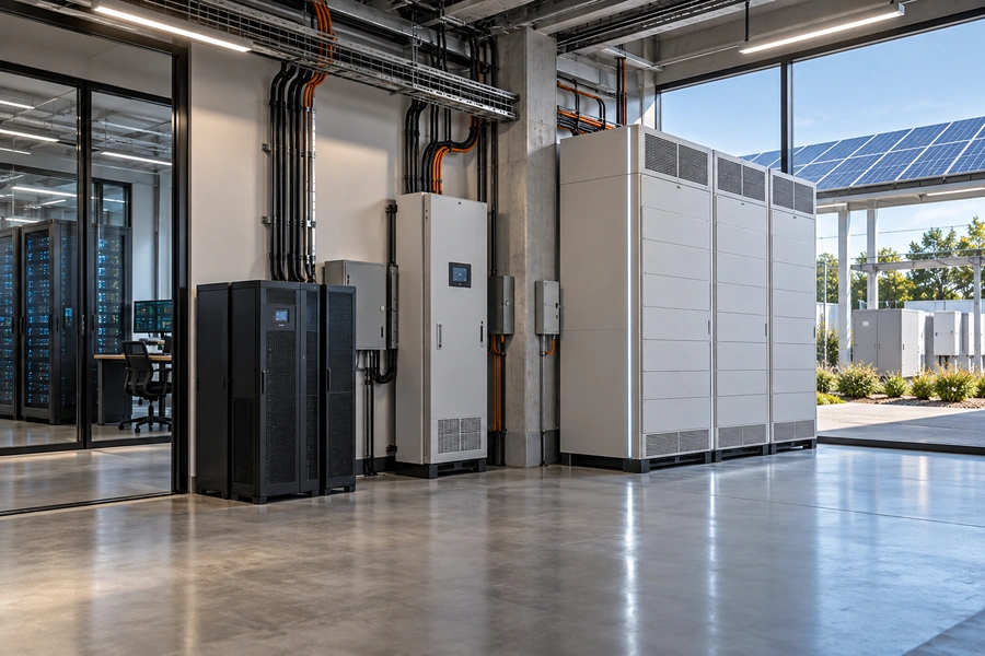
](https://voltcrave-battery.com/wp-content/uploads/2026/09/Integrating-UPS-and-Energy-Storage-Systems-Principles-Differences-and-Trends.webp)
Critical facilities need uninterrupted electricity, but they also face rising energy costs and renewable integration challenges. Keeping backup batteries idle wastes potential value, while aggressive cycling can threaten emergency reserves.
Integrating UPS and Energy Storage Systems combines critical-load continuity with broader energy management. A UPS primarily provides short-duration power during an input failure, while an ESS supports energy shifting, peak shaving, renewable integration, and grid flexibility. Successful integration requires coordinated batteries, power electronics, controls, and protected backup capacity so energy savings never compromise reliability.
The important change is therefore not that ESS is replacing UPS. Instead, the two technologies are becoming more coordinated. Batteries that once waited almost entirely for emergencies can increasingly participate in everyday energy management while maintaining sufficient capacity for critical backup.
What Is a UPS and How Does It Work?
A UPS is designed first around continuity rather than energy-market optimization.
An Uninterruptible Power Supply is a combination of converters, switches, and energy-storage devices that maintains load power when the normal input supply fails. Its main purpose is to protect critical equipment from interruptions, making UPS particularly important for data centers, healthcare, telecommunications, industrial controls, financial infrastructure, and other sensitive loads.
The simplest UPS architecture is:
Grid → UPS → Critical Load
Inside the UPS, there may be:
Rectifier → DC Bus/Battery → Inverter
When grid electricity is available, the system maintains the battery and supplies the protected load according to its topology.
When the normal source fails:
Battery → Inverter → Critical Load
The objective is continuity.
This differs from simply installing a backup generator. A generator requires starting, stabilization, and transfer. A UPS can support the load during this transition.
For example:
Grid Failure
↓
UPS Maintains Critical Load
↓
Generator Starts
↓
Generator Accepts Load
In a traditional application, the battery therefore spends much of its life:
waiting.
Its stored energy is valuable because it is available when something goes wrong.
That operating philosophy becomes important when comparing UPS with ESS.
What Is an Energy Storage System and How Does It Work?
An ESS uses stored energy more actively and for a broader range of purposes.
An Energy Storage System stores electricity and releases it when the energy has greater operational or economic value. A modern BESS typically combines battery cells, modules or racks, a Battery Management System, power conversion equipment, thermal management, protection, monitoring, and an Energy Management System to coordinate charging and discharging.
A simplified architecture is:
Grid ↔ PCS ↔ Battery
with:
BMS + EMS + Thermal Management + Protection
The battery provides:
kWh or MWh
of energy capacity.
The PCS provides:
kW or MW
of charge/discharge power.
The BMS monitors battery conditions.
The EMS decides how stored energy should be used.
A typical daily BESS schedule might be:
Morning → Hold/Charge
Midday → Charge From Solar
Afternoon → Peak Shaving
Evening → Energy Shifting
Night → Recharge or Maintain Reserve
Unlike a conventional standby UPS, an ESS may cycle frequently.
That makes:
efficiency,
cycle life,
usable SOC,
energy prices,
and:
battery degradation
much more important to its economics.
What Is the Difference Between UPS and ESS?
UPS and ESS can contain similar hardware, but similar components do not make them equivalent systems.
The fundamental difference is operating purpose. UPS prioritizes immediate continuity for critical loads when normal power fails. ESS prioritizes flexible energy storage and dispatch for applications such as peak shaving, renewable integration, energy shifting, and grid support. UPS traditionally remains on standby, while ESS may charge and discharge frequently during normal operation.
The distinction becomes clearer in a direct comparison:
| Factor | UPS | ESS |
|---|---|---|
| Primary Goal | Uninterrupted critical power | Energy management |
| Typical Battery Role | Emergency reserve | Active energy asset |
| Cycling Frequency | Traditionally low | Often frequent |
| Backup | Core function | Optional function |
| Peak Shaving | Not traditional core use | Common |
| Energy Shifting | Limited traditional use | Core application |
| Renewable Integration | Limited | Common |
| Grid Services | Limited | Possible/common |
| Critical Load Protection | Primary focus | Architecture-dependent |
| Typical Duration | Often short | Minutes to multiple hours |
| Control Priority | Continuity | Optimization within constraints |
| U.S. Product Standard | UL 1778 | UL 9540 |
UL notes that UPS and ESS share technologies such as batteries, inverters, and control electronics, but emphasizes that they have different intended functions and operating behavior.
This distinction should remain clear even as the technologies converge.
Why Are UPS and Energy Storage Systems Being Integrated?
The economic opportunity comes from using stored energy more productively without reducing backup readiness.
UPS and ESS integration is becoming attractive because facilities increasingly want battery capacity to provide both resilience and economic value. Instead of leaving all stored energy idle while waiting for an outage, part of the battery capacity can potentially support peak shaving, energy shifting, renewable self-consumption, or grid flexibility while a protected reserve remains available for emergencies.
Consider a battery with:
1,000 kWh usable capacity.
The facility requires:
400 kWh
of guaranteed backup reserve.
Potentially flexible energy:
1,000 – 400 = 600 kWh
Instead of leaving the entire:
1,000 kWh
unused during normal operation, the system could potentially use part of the:
600 kWh
for energy management.
The central rule becomes:
Economic Dispatch Must Not Consume Required Backup Reserve
This changes the battery from:
Passive Backup Asset
into:
Backup + Energy Management Asset.
The potential benefit is higher utilization of expensive battery infrastructure.
However, the integration only makes sense when the battery, power electronics, controls, safety architecture, and warranty are designed for the additional operating duty.
What Are the Main Ways to Integrate UPS and ESS?
There is no single universal UPS-ESS architecture.
UPS and ESS can be integrated through coordinated separate systems, a common microgrid controller, shared DC infrastructure, or battery architectures that reserve part of their capacity for critical backup while using the remainder for energy management. The appropriate approach depends on reliability requirements, transfer performance, battery chemistry, power rating, runtime, certification, and site architecture.
A conservative architecture keeps the systems separate:
Grid → UPS → Critical Loads
and:
Grid ↔ ESS ↔ Facility Loads
The two systems can communicate but remain electrically distinct.
A broader architecture could be:
Grid + Solar + ESS + Generator → Microgrid Bus
with:
UPS → Most Sensitive Loads
Here, the ESS manages the larger facility while the UPS provides another layer of protection.
A more integrated architecture might allow battery resources to support both:
critical-power reserve
and:
economic dispatch.
The deeper the integration becomes, the more important control hierarchy becomes.
The system should prioritize:
Safety
↓
Critical-Load Continuity
↓
Backup Reserve
↓
Power Quality
↓
Energy Optimization
This order is essential.
Electricity savings should never become more important than maintaining power to a critical load.
What Is Reserved State of Charge in UPS-ESS Integration?
Reserved SOC creates a boundary between battery capacity used for economics and battery capacity protected for emergencies.
Reserved State of Charge is a battery capacity threshold that the control system protects from routine economic discharge. In an integrated UPS-ESS, the EMS can use energy above this reserve for peak shaving or energy shifting while maintaining sufficient stored energy below the operating range for the required emergency backup duration.
Suppose:
Battery capacity = 2 MWh
Required emergency reserve = 40%
Protected energy:
2 × 0.40 = 0.8 MWh
Potentially dispatchable energy:
2 – 0.8 = 1.2 MWh
The normal operating window might therefore be:
40% SOC → 90% SOC
rather than:
0% → 100%.
Why not operate across the entire battery?
Because an outage could occur immediately after an economic discharge event.
Imagine:
4:00 PM — Electricity price is high
The EMS discharges aggressively.
Then:
4:15 PM — Grid fails
If the battery has been depleted, the facility may no longer have its required backup.
Reserved SOC prevents this conflict.
The battery's state of charge becomes a reliability parameter, not merely an energy metric.
Can an ESS Replace a UPS?
Large battery capacity alone does not guarantee UPS-level continuity.
An ESS can provide backup functionality, but it should not automatically be considered a replacement for a dedicated UPS. UPS performance depends on transfer behavior, power quality, inverter response, fault handling, critical-load compatibility, and product requirements—not simply stored kWh. An ESS must be specifically engineered for the required continuity performance if it is expected to perform a UPS-like role.
Consider:
ESS capacity = 10 MWh
UPS battery capacity = 500 kWh
The ESS contains:
20 times more energy.
Does that automatically make it the better UPS?
No.
A sensitive data center load may require:
extremely fast response,
stable voltage,
stable frequency,
appropriate harmonic performance,
and:
specific fault behavior.
A large grid-connected ESS may not have been designed around those requirements.
Therefore:
Energy Capacity ≠ Continuity Performance
A better equation is:
Critical Backup Capability = Energy + Power + Response + Power Quality + Switching + Controls + Protection
The ESS can potentially become part of the critical-power architecture.
But replacing the UPS requires much more than increasing battery capacity.
Can UPS Battery Capacity Be Used for Peak Shaving?
This is one of the most interesting integration opportunities.
UPS battery capacity can potentially support peak shaving when the battery and power electronics are designed for additional cycling and when sufficient backup reserve is always maintained. The economic opportunity depends on demand charges, peak duration, battery power, available energy above the reserve threshold, degradation, and facility reliability requirements.
Suppose facility demand is normally:
1 MW
but reaches:
1.3 MW
for one hour.
Target grid demand:
1.1 MW
Required battery output:
1.3 – 1.1 = 0.2 MW
or:
200 kW
For one hour:
200 kW × 1 h = 200 kWh
Now suppose total battery capacity is:
800 kWh.
Required emergency reserve:
400 kWh.
Potential flexible capacity:
800 – 400 = 400 kWh
The 200 kWh peak-shaving event could theoretically fit within the flexible energy window.
After the peak:
Battery → Recharge
while maintaining the emergency reserve policy.
This can convert previously idle capacity into a source of operating savings.
But it also creates more battery cycling.
The additional degradation must therefore be included in the economic calculation.
How Can UPS-ESS Integration Reduce Electricity Costs?
The main financial opportunity is value stacking.
An integrated UPS-ESS can reduce electricity costs through peak shaving, time-of-use energy shifting, solar self-consumption, demand response, and potentially other grid services. By combining these functions with backup capability, facilities can increase battery utilization, but the financial value must be weighed against conversion losses, additional cycling, degradation, maintenance, and required emergency reserves.
Suppose a facility pays:
$25/kW/month
for demand charges.
Battery peak reduction:
200 kW
Monthly gross savings:
200 × $25 = $5,000
Annual:
$5,000 × 12 = $60,000
Now assume the battery also shifts:
500 kWh/day
from a lower-cost period into a period where electricity is:
$0.10/kWh more valuable.
Simplified daily gross value:
500 × $0.10 = $50
Annual gross value:
$50 × 365 = $18,250
Combined:
$60,000 + $18,250
= $78,250/year
before losses, degradation, maintenance, and other costs.
The battery is now creating:
Reliability Value + Energy Value
rather than reliability value alone.
How Do Solar and Renewable Energy Work With Integrated UPS-ESS?
Renewable generation can turn backup duration from a fixed battery-runtime calculation into a dynamic energy balance.
Solar and other onsite generation can work with an integrated UPS-ESS by supplying loads directly, charging batteries during surplus periods, and potentially replenishing storage during grid outages. When the system supports islanded operation, renewable generation can extend backup duration beyond what the battery could provide from its initial SOC alone.
A resilient architecture could look like:
Grid + Solar + ESS + Generator → Facility
with:
UPS → Critical Loads
During normal conditions:
Solar → Facility
Surplus solar:
Solar → Battery
During high electricity prices:
Battery → Facility
During a grid outage:
UPS/ESS → Critical Loads
During daylight:
Solar → Loads + Battery Recharge
If the outage continues:
Generator → Loads/Battery
Consider a:
500 kW
critical load.
For eight hours without recharge:
500 kW × 8 h = 4 MWh
of theoretical energy.
Now suppose solar provides:
1 MWh
during that period.
Net battery/generator energy requirement becomes approximately:
4 – 1 = 3 MWh
before system losses and timing constraints.
This illustrates why UPS-ESS integration increasingly overlaps with:
microgrid design.
What Role Does the EMS Play in UPS and ESS Integration?
As systems become more integrated, software becomes part of the reliability architecture.
The Energy Management System coordinates battery dispatch using facility demand, electricity prices, renewable generation, battery SOC, backup requirements, grid status, and equipment constraints. In an integrated UPS-ESS, the EMS must optimize energy use while enforcing reserve limits and ensuring that economic operation does not interfere with critical-power requirements.
The EMS may receive:
Grid Status
Load Data
Solar Forecast
Electricity Tariff
Battery SOC
Battery Temperature
UPS Status
Generator Status
Then decide:
Charge
Discharge
Hold
Maintain Reserve
or:
Island
Suppose:
SOC = 75%
Reserve threshold = 40%
Demand charge event = active
The EMS may discharge.
Later:
SOC = 41%
The economic dispatch should stop.
Now suppose:
Grid Failure
The protected battery reserve remains available.
This is why the control hierarchy matters:
Safety > Reliability > Economic Optimization
An algorithm that produces excellent electricity savings but leaves insufficient backup capacity is not a successful UPS-ESS strategy.
How Do BMS, PCS, and EMS Differ?
These three systems are often discussed together, but they perform different functions.
The BMS manages battery safety and cell conditions, the PCS converts electrical power between the battery and AC system, and the EMS coordinates when and how the storage system operates. In an integrated UPS-ESS, all three must work together while also communicating with switchgear, generators, renewable sources, building controls, and critical-power infrastructure.
The division can be simplified as:
BMS — Is the Battery Safe?
It monitors:
cell voltage,
temperature,
current,
SOC,
and:
fault conditions.
PCS — How Much Power Moves?
It controls:
charging,
discharging,
DC/AC conversion,
and:
power flow.
EMS — When Should Energy Move?
It decides based on:
tariffs,
loads,
renewable generation,
backup reserve,
and:
operating objectives.
The complete control chain becomes:
EMS → PCS → Battery
while:
BMS → Battery Protection
can override commands when operating conditions become unsafe.
For critical infrastructure, this hierarchy must be clearly engineered.
Why Is LFP Important for UPS-ESS Integration?
Frequent battery cycling changes the chemistry requirements compared with traditional standby operation.
LFP is increasingly important in integrated UPS-ESS applications because stationary storage benefits from its cost competitiveness and suitability for frequent cycling. The IEA reports that LFP accounted for around 90% of battery-storage deployments in 2025, while battery-based UPS capacity also expanded strongly, particularly in data-center applications.
Traditional UPS installations have frequently used:
lead-acid batteries.
That technology remains important.
However, a battery used mainly for:
standby backup
experiences a very different duty cycle from a battery used for:
daily peak shaving + solar shifting + backup.
Once frequent cycling is introduced, characteristics such as:
cycle performance,
usable capacity,
efficiency,
energy density,
and:
thermal management
become more important.
The IEA reports that LFP now represents approximately:
90%
of battery-storage deployments.
This does not mean LFP is automatically the correct chemistry for every UPS.
It means the growth of frequent-cycling ESS is increasingly shaping battery technology choices.
What Safety Standards Apply to UPS and Energy Storage Systems?
Integration can bring two historically distinct standards environments into the same project.
In the United States, UPS products are associated with UL 1778, while UL 9540 is the foundational product safety standard for Energy Storage Systems and Equipment. UL 9540A evaluates thermal-runaway and fire-propagation behavior in battery ESS, and NFPA 855 addresses stationary ESS installation requirements. Integrated projects must determine which requirements apply to each part of the architecture.
For UPS:
UL 1778
addresses Uninterruptible Power Systems.
For ESS:
UL 9540
covers Energy Storage Systems and Equipment.
For stationary batteries:
UL 1973
addresses batteries used in stationary and motive auxiliary applications.
For thermal-runaway testing:
UL 9540A
provides the test method used to evaluate thermal runaway and fire propagation behavior.
And:
NFPA 855
addresses stationary ESS installation.
These are not interchangeable standards.
The applicable requirements depend on:
product architecture,
installation,
battery type,
system function,
location,
and:
local code adoption.
What Changed in BESS Fire Safety in 2026?
The safety framework continues to evolve as battery installations become larger and more common.
The 2026 edition of NFPA 855 strengthens the emphasis on fire and large-scale fire testing for stationary ESS, while UL 9540A remains the referenced method for evaluating thermal-runaway and fire-propagation behavior. The sixth edition of UL 9540A, published in March 2026, adds an updated installation-level large-scale fire-test method aligned with NFPA 855 guidance.
This is particularly relevant for large:
commercial,
industrial,
data-center,
and:
containerized BESS
projects.
UL reports that the 2026 NFPA 855 edition includes updated expectations around large-scale fire testing, including scenarios where fire could spread from one BESS to another.
The sixth edition of UL 9540A was published:
March 13, 2026.
For integrated UPS-ESS projects, this means battery expansion should not be treated only as an electrical-engineering decision.
Increasing battery capacity may also affect:
fire testing,
separation distances,
enclosure design,
fire suppression,
venting,
and:
permitting.
Safety therefore becomes a system-level design consideration.
Are Data Centers Driving UPS and ESS Integration?
Data centers provide one of the strongest use cases because they combine extremely high reliability requirements with rapidly growing electricity consumption.
Data centers are helping accelerate UPS-ESS convergence because they already deploy substantial battery capacity for continuity while also facing high energy demand, peak power requirements, and growing interest in grid flexibility. The IEA reports that battery-based UPS capacity additions, primarily serving data centers, increased 30% to 45 GW in 2025.
The traditional data-center architecture relies on layers of resilience.
For example:
Grid
↓
UPS
↓
IT Load
with:
Generator
providing longer-duration backup.
But the broader energy architecture can increasingly include:
Grid + BESS + Renewables + Generator + UPS
The UPS protects sensitive IT loads.
The BESS can potentially support:
peak demand,
renewable integration,
grid interaction,
and:
facility-level resilience.
The generator remains available for extended outages where required.
Instead of treating these technologies as isolated assets, a controller can coordinate them.
This creates:
layered resilience.
UPS and ESS do not necessarily compete.
They can perform different jobs inside the same power architecture.
Can Integrated UPS-ESS Reduce Generator Use?
Batteries can handle short events efficiently, while generators remain useful for longer-duration energy requirements.
UPS-ESS integration can reduce generator starts and runtime by using stored battery energy for short outages, transition periods, peak events, and renewable-energy balancing. However, long-duration outages may still require generators or substantial renewable generation because battery runtime remains limited by stored kWh.
Suppose critical load is:
1 MW
Available battery energy:
4 MWh
Theoretical runtime:
4 ÷ 1 = 4 hours
For a:
20-minute outage,
the battery may be sufficient.
For:
24 hours,
the theoretical energy requirement becomes:
1 MW × 24 h = 24 MWh
The battery is insufficient.
A layered architecture becomes more practical:
UPS → Instant Continuity
ESS → Short/Medium-Duration Energy
Generator/Renewables → Extended Operation
This is an important trend.
The goal is not necessarily to eliminate every generator.
It is to assign each technology to the job it performs well.
What Are the Main Challenges of UPS-ESS Integration?
Integration creates opportunities, but it also introduces additional technical and operational complexity.
The main UPS-ESS integration challenges include protecting emergency SOC, coordinating multiple converters and controllers, managing additional battery degradation, maintaining power quality, meeting UPS and ESS safety requirements, avoiding new single points of failure, and ensuring that financial optimization never reduces the reliability of critical loads.
Battery degradation is one obvious issue.
Traditional battery:
few emergency cycles
Integrated battery:
potentially hundreds of partial or full cycles per year
That changes:
warranty,
lifetime,
thermal load,
and:
replacement economics.
Another challenge is control failure.
Suppose one EMS coordinates:
UPS,
BESS,
solar,
and:
generator.
If that controller becomes unavailable, what happens?
A resilient design should provide:
fail-safe operating modes.
Another issue is forecasting.
If the EMS expects:
low outage risk
and discharges the battery for:
peak shaving,
the grid can still fail unexpectedly.
This is why:
protected reserve
should be based on reliability requirements rather than predictions alone.
Integration should eliminate wasted capacity without creating fragile architecture.
What Are the Major UPS and Energy Storage Trends in 2026?
The industry is moving toward more battery deployment, longer storage duration, LFP, smarter controls, and greater coordination between backup and energy-management assets.
Major 2026 trends include rapid BESS deployment, strong growth in battery-based UPS for data centers, LFP dominance in stationary storage, longer battery durations, more energy shifting, intelligent EMS, renewable integration, and increasingly sophisticated fire-safety requirements. Together, these trends are moving batteries from passive backup devices toward actively managed resilience and flexibility assets.
The numbers illustrate the transition.
Global battery-storage additions reached:
108 GW in 2025
which was:
40% higher than 2024.
Installed battery-storage capacity became:
11 times higher than in 2021.
LFP reached approximately:
90% of deployments.
Most battery projects still cluster around:
two hours
but more systems are reaching:
four hours or longer.
At the same time, battery-based UPS—primarily in data centers—added:
45 GW in 2025,
with additions rising approximately:
30%.
The direction is clear.
Backup storage is growing.
Active energy storage is growing.
And the control systems connecting them are becoming more important.
My Insights: Integrating UPS and Energy Storage Systems—What Are the Principles, Differences, and Trends
The most important development is not the disappearance of UPS or the simple expansion of BESS. It is the emergence of coordinated power architectures where reliability and energy management can coexist.
Integrating UPS and Energy Storage Systems combines the UPS principle of immediate critical-load continuity with the ESS principle of flexible energy dispatch. Their main difference remains operating purpose, but 2026 trends—including LFP growth, data-center UPS expansion, longer-duration BESS, smarter EMS, and evolving safety requirements—are driving greater coordination between the two.
My First Insight: The Difference Is Primarily About Operating Priority
UPS asks:
“How do I keep this critical load operating?”
ESS asks:
“When is this stored energy most valuable?”
Integrated systems ask both questions.
But the priority should remain:
Critical Power First
and:
Energy Optimization Second.
This distinction should guide every design decision.
My Second Insight: Reserved SOC Is the Key Integration Mechanism
The simplest conceptual equation is:
Total Usable Battery = Reliability Reserve + Flexible Energy
Suppose:
Total usable energy = 2 MWh
Required backup = 800 kWh
Then:
Flexible capacity = 1.2 MWh
That 1.2 MWh can potentially generate everyday value.
The 800 kWh remains protected.
This is how one battery resource can serve two objectives without treating every stored kWh identically.
My Third Insight: Software Is Becoming Part of the Critical-Power Architecture
In a traditional UPS, control is focused heavily on:
continuity.
In a modern integrated system, software may coordinate:
grid,
UPS,
BESS,
solar,
generator,
tariffs,
SOC,
and:
facility load.
The EMS is therefore no longer merely:
an energy-saving tool.
It can become part of the site's broader resilience architecture.
That also means EMS failure modes, cybersecurity, communication reliability, and control hierarchy deserve greater engineering attention.
My Fourth Insight: Integration Should Create Layered Resilience, Not One Giant Battery
There is a temptation to assume:
larger battery = better resilience.
A better architecture may be:
UPS → Immediate Protection
BESS → Energy Management + Medium-Duration Backup
Solar → Renewable Recharge
Generator → Long-Duration Contingency
Each technology handles the task it performs well.
This can be more resilient than attempting to force one storage system to perform every function.
My Fifth Insight: Integrating UPS and Energy Storage Systems—Principles, Differences, and Trends
This directly answers the H1.
| Dimension | UPS | ESS | Integrated Direction |
|---|---|---|---|
| Core Principle | Maintain continuity | Store and optimize energy | Protect loads while optimizing available energy |
| Primary Objective | Reliability | Flexibility/economics | Reliability + flexibility |
| Battery Behavior | Primarily standby | Frequent cycling | Protected reserve + active capacity |
| Response Requirement | Extremely fast for critical loads | Application-dependent | UPS-level protection retained where required |
| Typical Duration | Short | Minutes to hours | Layered duration |
| Peak Shaving | Traditionally uncommon | Common | Possible with flexible capacity |
| Energy Shifting | Traditionally uncommon | Core application | Increasingly valuable |
| Renewable Integration | Secondary | Major use | Solar + ESS + critical power |
| Emergency SOC | Primary battery purpose | One operating constraint | Explicit protected reserve |
| Generator Role | Common bridge/backup partner | Optional | Long-duration resilience layer |
| BMS | Battery protection | Battery protection | Coordinated health and safety |
| PCS/Inverter | Critical power conversion | Bidirectional energy conversion | Architecture-specific coordination |
| EMS | Historically limited | Central | Increasingly important |
| UPS Standard | UL 1778 | — | Still relevant to UPS function |
| ESS Standard | — | UL 9540 | Relevant to ESS function |
| Fire Testing | Architecture-dependent | UL 9540A | Increasingly important as battery scale grows |
| 2026 Trend | Battery-based UPS growing | BESS growing rapidly | Increasing coordination |
| Battery Chemistry Trend | Lead-acid historically important; lithium-ion expanding | LFP dominant | More frequent-cycling lithium-ion applications |
The architecture can be summarized as:
UPS Reliability + ESS Flexibility + EMS Intelligence = Integrated Energy Resilience
But the order matters.
A facility should not begin by asking:
“How much money can our UPS batteries make?”
It should begin with:
“How much stored energy must remain available to protect critical loads?”
Only after that requirement is established should the remaining capacity be considered for:
peak shaving,
energy shifting,
solar self-consumption,
demand response,
or:
other services.
For example:
Total battery = 5 MWh
Protected reserve = 2 MWh
Flexible energy = 3 MWh
During normal operation:
3 MWh Flexible Capacity → Energy Optimization
while:
2 MWh Reserve → Protected
During an outage:
Economic Optimization Stops
and:
Battery → Critical Loads
If solar is available:
Solar → Loads + Battery
If the outage becomes prolonged:
Generator → Loads + Battery Support
When grid service returns:
Grid → Facility + Recharge
Then:
Normal Energy Optimization Resumes
This operating model explains the real convergence between UPS and ESS.
The UPS does not become irrelevant.
The ESS does not simply replace it.
Instead:
UPS protects continuity.
ESS provides energy flexibility.
BMS protects battery operation.
PCS manages power conversion.
EMS coordinates energy strategy.
Renewables provide additional energy.
Generators provide extended-duration contingency where required.
Together, these technologies form a more complete:
critical energy management system.
The latest market data support this direction. Battery storage was the fastest-growing power technology in 2025, with 108 GW of new capacity, while battery-based UPS additions—primarily serving data centers—also increased strongly. LFP now represents around 90% of battery-storage deployments, and project durations are gradually increasing.
Safety requirements are evolving at the same time. The 2026 NFPA 855 framework places greater emphasis on large-scale fire testing, while the updated UL 9540A methodology provides a more rigorous installation-level approach for evaluating fire propagation in BESS.
These changes point toward the same conclusion:
The future of critical power is not simply:
UPS
or:
ESS.
It is increasingly:
UPS + ESS + EMS + Renewables + Backup Generation
working as coordinated layers.
The principle is continuity.
The difference is how stored energy is normally used.
The trend is integration.
Conclusion
UPS protects critical loads while ESS manages energy flexibly. Their integration can improve resilience and battery utilization when reserve SOC, controls, power quality, safety, and reliability remain properly engineered.
](https://voltcrave-battery.com/wp-content/uploads/2026/09/How-to-Choose-the-Best-Lithium-Battery-for-Off-Grid-Solar-Power-768x512.webp)
](https://voltcrave-battery.com/wp-content/uploads/2026/10/Which-Power-Bank-Is-Best-for-Outdoor-Use-in-2026-768x512.webp)
](https://voltcrave-battery.com/wp-content/uploads/2026/10/What-Are-the-Disadvantages-of-a-Portable-Power-Station-768x512.webp)